


Automatic Top Plate Cartesian Coordinate Manipulator
Overall requirements Of Automatic Top Plate Cartesian Coordinate Manipulator
1. Design a two-axis Cartesian coordinate handling robot, which can carry out two-dimensional automatic handling of workpieces.
2. The robot adopts truss type, single Z-axis structure, and holds the fixture in the form of claw.
3. Single workpiece specifications: diameter 230mm, width 1000mm, weight 60kg.
4. The two-axis handling robot must complete a handling work within the specified time.
Technical solutions of Automatic Top Plate Cartesian Coordinate Manipulator
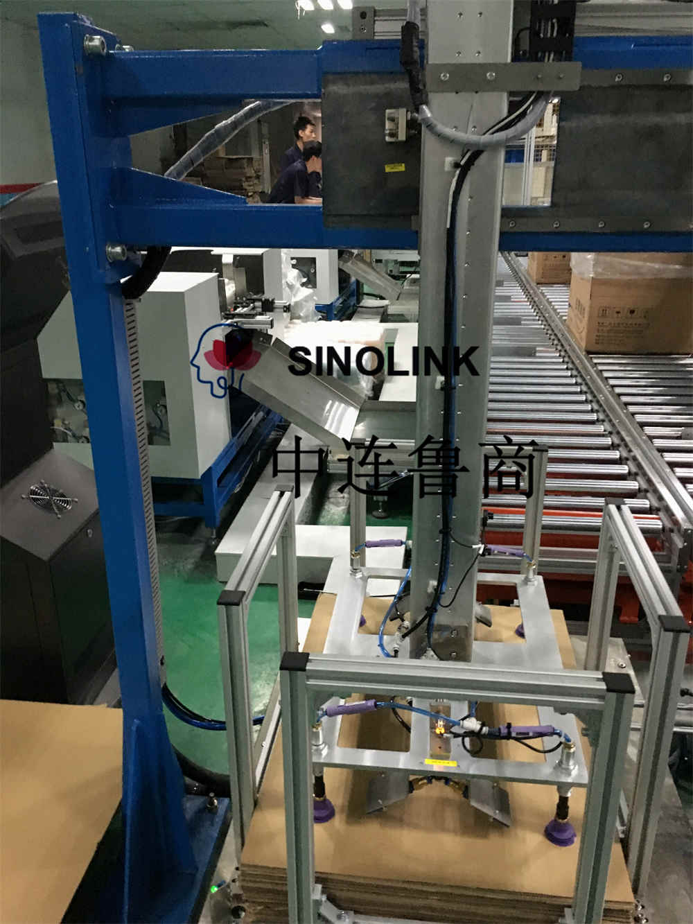
Figure 1 is the overall layout of the recommended two-axis handling robot solution. The main parts it contains are as follows:
1. A two-axis handling robot.
2. Robot base and bracket.
3. Robot control system and electrical box, etc.
4. Robot safety protection net, etc.

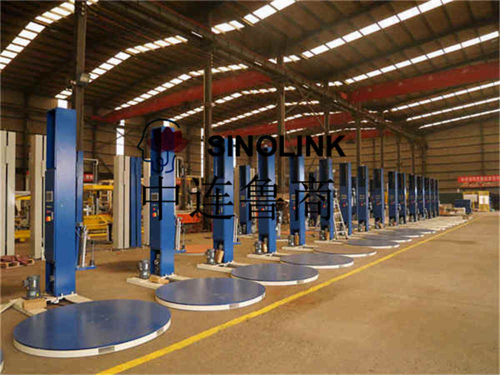
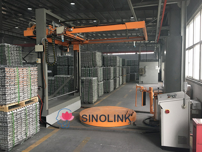
The X-axis and Z-axis definitions of the robot are shown in Figure 1, and the gripper mechanism is to be designed. This plan is only a preliminary plan, which should be revised and improved after further discussion and demonstration by both parties. The final design is designed at your company until both parties are satisfied. Figure 2 shows past cases for reference.
Introduction to the main parts of the robot
1. X-axis of the robot:
We use a linear motion unit as the X-axis, which uses a precision toothed belt drive for load transmission. It can be used alone or in parallel with two gantry transmission linear motion units. The linear motion unit is fixed on a plane, and the slider motion motor does not move, which can be used for long-distance movement on the plane.
The two shared robots move forward and backward stroke: 6000mm
Two shared robots moving up and down stroke: 500mm
Forward and backward movement stroke of a single robot: 3000mm
Two shared robots moving up and down stroke: 500mm
Front and rear movement: motor drive, drive motor power 1.5kw
Up and down movement: motor drive, drive motor power 1.5kw
2. Robot Z-axis scheme:
The Z-axis adopts a linear motion unit with a rotary axis, two linear guide guides, precision synchronous belt drive, and the specific parameters of the Z-axis with a single standard slide are the same as those of the X-axis. The actual diagram is shown in Figure 4. The servo motor is an AC servo motor with a holding brake.

3. Robot base
It adopts the method of welded parts and connects with the ground through the anchors. The base model diagram and the physical diagram are shown in Figures 5 and 6.


4. Control system
The control system of the robot adopts Siemens PLC, and the specific model, the number of supporting touch screen HMI and I/O ports are determined according to specific needs.
1. The work to be completed by the PLC control system
1) Realize the control function of the handling and feeding process
2) With manual and automatic loading and unloading control function
3) Reprogramming and optimization of production process (with password)
4) It is necessary to set the safe zone function, detect the sensor signal in place of each action in all actions and coordinate the handshake with the spinning machine at the signal level.
5) You can choose PLC with Ethernet communication function or Profibus function to achieve data management.
6) Parameters can transfer data and programs through USB, CF card and other media
7) Multi-axis movement can be performed at the same time
8) High stability, high running speed, high acceleration and deceleration.

More information, please contact with us at any time.
Ady
WhatsApp:+86 15634865861

Related Products


Submitted successfully
We will contact you as soon as possible
Related News
Popular products
Submitted successfully
We will contact you as soon as possible