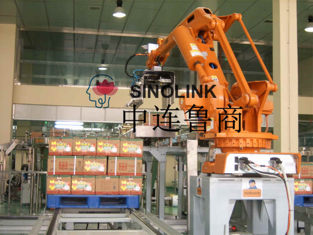
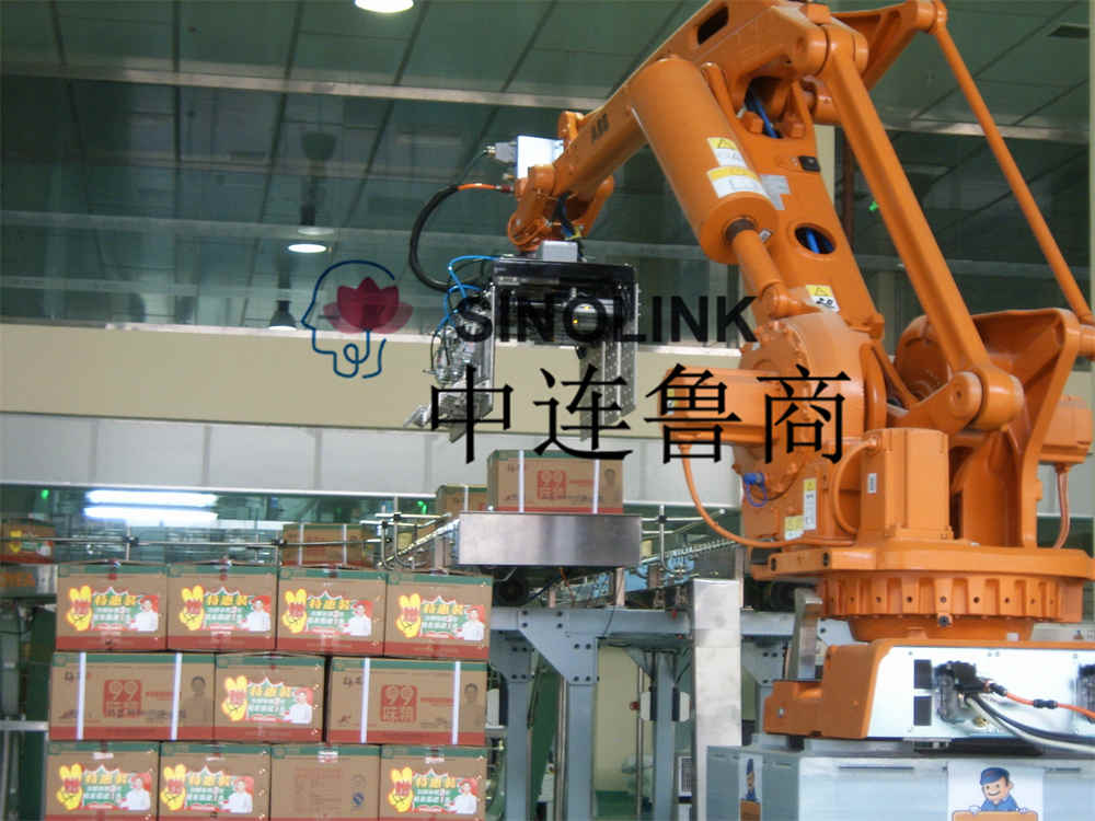
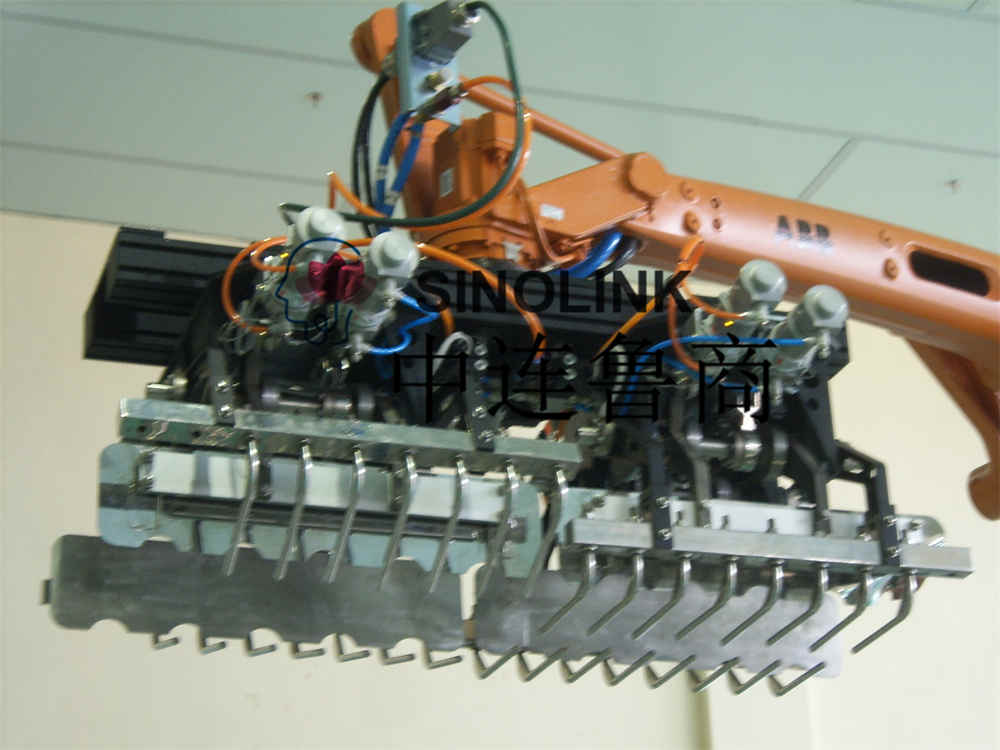
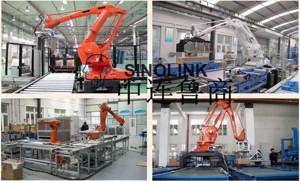
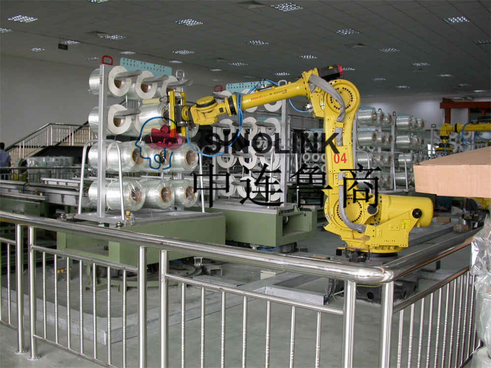
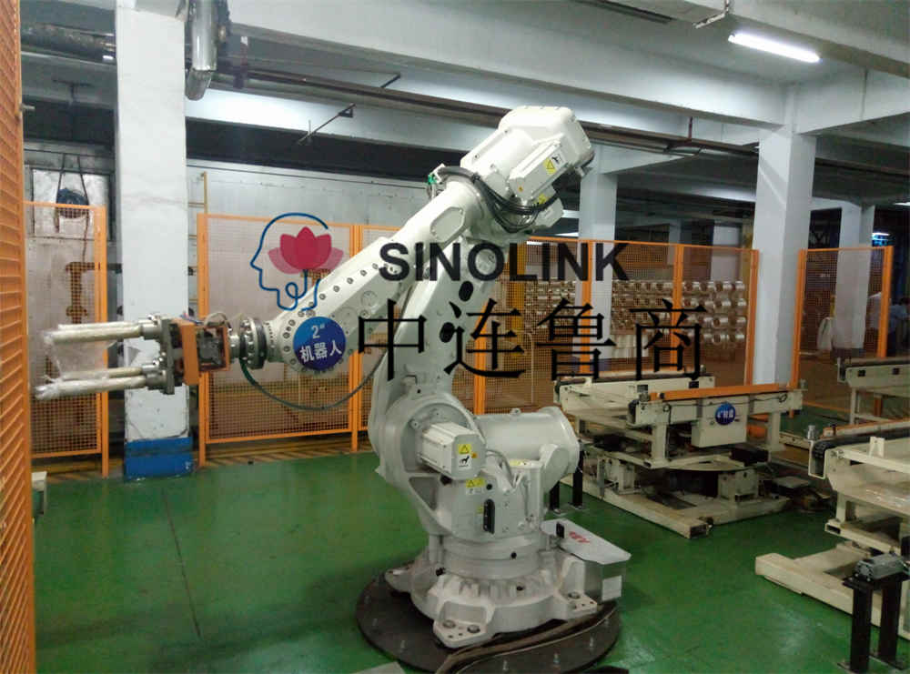
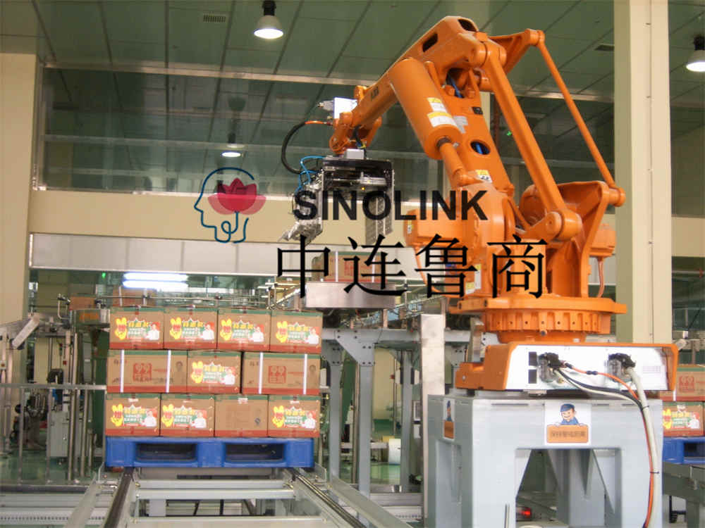
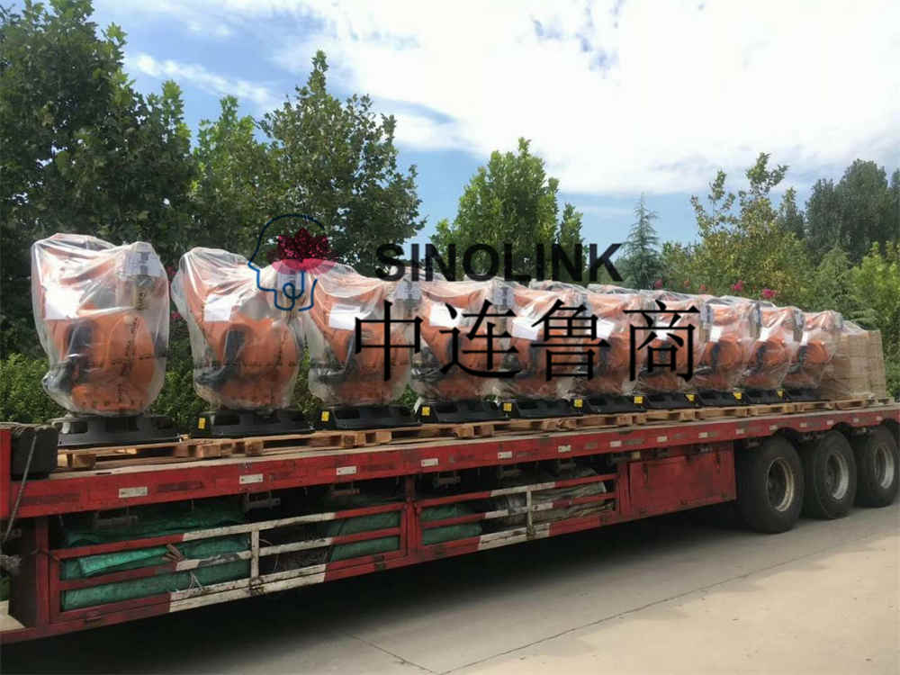
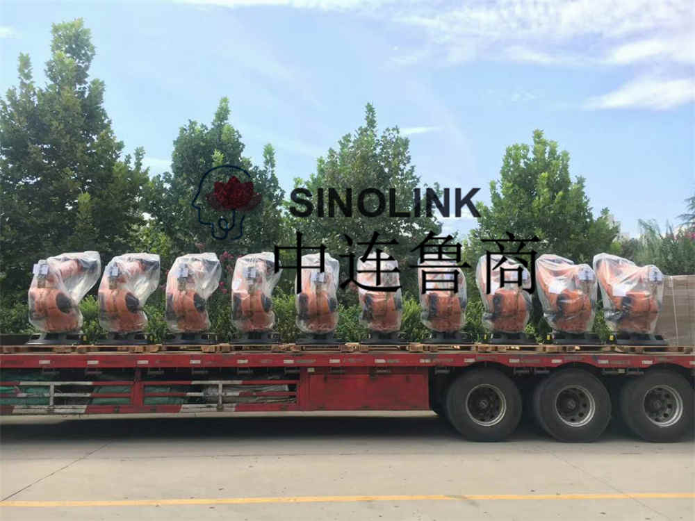
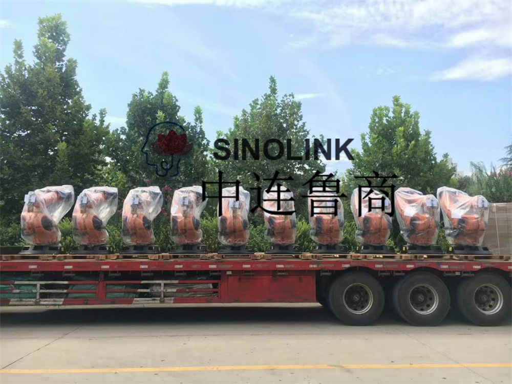
Robotic Or Manipulator Handling, Depalletizing, Palletizing Systems
Robotic Or Manipulator Handling, Depalletizing, Palletizing Systems
A Part Of Technical Requirements For Palletizing Manipulator + Wrapping Machine
1、The goods provided must be brand new, flawless products, and must comply with relevant national standards and express guarantees.
2. The goods provided must meet the requirements of our company, and must be docked with the production lines of the warehouse, automated three-dimensional warehouses and four-way vehicle shelves to ensure that the products are normally stored after they are off the line.
1. Outline of equipment
Constructions of equipment are as follows.
No. | Equipment | Q’ty | Description |
1 | Robot | 1 | Without robot base |
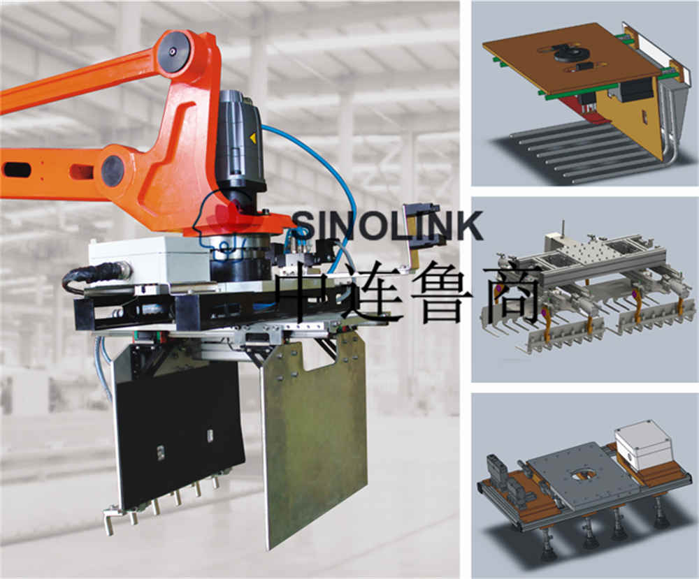
2 | Standard Hand | 1 | |
3 | Control box | 1 | |
4 | Manual teaching box | 1 | With 10m cable |
5 | Emergency stop | 2 | 1 on control box and 1 on teaching box |
6 | Cable between control box and robot | 1 | 10m |
7 | Teaching memory | Max 120 blocks, 90steps×90layers ※Condition ”blocks”×”steps”×”layers” ≦45,000 | |
8 | External interlock signals | Please refer to Interlock List in electrical drawings for the kinds. |
2. General specifications
Layout type: Please refer to Layout Drawing attached.
1) Details of products to handle
Package type: Box
a. Contents:
Size, weight and number of pieces/pallet
N0. | Product | Size and weight | Number of pieces/pallet |
W×L×H – Weight(kg) | Pieces/layer×layers =bag/pallet | ||
1 | 255Wx370Lx260H-17kg | 10boxsx 6layers=60boxs/pallet |
2) Stacking height: 1560 mm(pallet not included)
3) Handling capacity: 200-400 boxes/hour
※Condition
Pallet exchange time not taken into account.
4) Pallet size: 1000 (W)×1200 (L)×150 (H)
5) Stacking patterns:
Refer to the drawings attached.
3. Installation environment
1) Installation place: indoor
2) Surrounding temperature: normal(0℃~40℃)
3) Relative humidity: normal(45%RH~85%RH)
4) Atmosphere: normal (no special environment requiring rust-preventive or explosion-proof measures, or measures against extremely low temperature)
4. Power source
1) Required power source
3 phases, 3 wires, 220V,50Hz(Max. fluctuation±10%)
a. Control power shall be 220V or 100V single phase, which is obtained from R and S phases of main power source. Special DC source is used for energizing the microcomputer.
b. The earth terminal is installed in the control box. Please connect the earth wire with the earth terminal in the same way as the power cable.
2) Required power consumption: FUJI ACE 2.3KVA
5. Air source
1) Required air pressure: 0.5Mpa(higher than gauge pressure)
2) Required air consumption消耗量: FUJI ACE 120Nl/min
3) Compressed air will be received at the union 3/8B(pipe size), which is installed on the compressed-air post.
6. Control box specifications
1) Material: thick steel plate-2.3mm (door-1.6mm)
2) Structure: self-standing type dust-proof structure (front door type)
3) External dimensions: 700W×350D×1700H
4) Language use: English ,Chinese
5) Supply scope of auxiliary equipment
Device | In-scope | Out-scope | Device 元件 | In-scope 有 | Out-scope 无 |
Circuit breaker | ○ | Light inside control box | ○ | ||
Motor breaker | ○ | Electric outlet | ○ | ||
Leakage breaker | ○ | Programming unit | ○ |
6) Wire size in control box :
We reserve the right to select suitable wire makers.
Control circuit: 0.75Sq(AWG28 or more for small electric current circuit and 0.5~0.75Sq for I/O circuit)
a. Power circuit :
Motor capacity
| (0.2~1.5kw) | (2.2~3.7kw) | (5.5kw) |
AC200/220 | 1.25Sq or more | 2Sq | 3.5Sq |
Motor capacity | (0.2~2.5kw) | (2.5~4.5kw) | |
AC servo motor | 1.25Sq or more | 2Sq |
7) Wire colors :
Power circuit | Black (our standard) |
Control circuit (AC) | Yellow |
Control circuit (DC) | Blue |
Earth wire | Green |
8) Phase colors :
R phase R | Red |
S phase S | White |
T phase T | Blue |
9) Lamp and button colors :
Run | Stop | Power ON | Breakdown | Signal | Others | |
Lamp | - | - | - | - | - | - |
Button | - | - | - | - | - | - |
10) General information :
a. In the control box, round solder fewer terminals are used for power circuits and Y shape solder fewer terminals are used for control circuits.
b. No more than 2 wires are connected at the same terminal.
c. All the wire tubes are marked with the same number used in the sequence except for those of power circuits. Insulation caps with identifying colors are used for power circuits.
More information or requirement, please talk with us at any time.
Ady
WhatsApp:+86 15634865861
Related Products
Submitted successfully
We will contact you as soon as possible


